
How do I size my aquarium stand to hold my fish tank?
A practical lesson to show the average aquarist how to size the load bearing members of an aquarium stand. We will learn how to answer the often asked question “What size wood do I need to use for my aquarium stand” or “how many supports do I need for a 6 foot long tank”, etc.
This is not an in depth physics or engineering lesson aimed at textbook definitions or deep understanding of the physics or maths or the derivation of formulas, but rather a simplified overview of the concepts involved in determining how much something (in this case a simply supported beam) will deflect under a uniform load. The goal is to give you (the reef aquarium owner) the tools to design your own aquarium stand or anything else where a simple beam deflection calculation can be used.
Already understand and just looking for the calculator?
*this is not an article about stand design. The focus here is simply for those looking to understand how to size the load bearing members in an aquarium stand or other beam application. Please read and agree to the disclaimer before using this information.
Design Considerations
We need to understand (or rather apply) some basic concepts to determine how much a beam will deflect (bend) under load. In this case under the weight of the aquarium that is sitting on it. Questions that need to be answered before we do the calculations.
- How is the beam supported?
- How far will be beam span?
- How stiff is the shape of the beam?
- How stiff is the material used for the beam?
- How much weight is on the beam and bow is it distributed?
Each of these answers is actually quite easy to obtain. Each of these items will be explained below. Our model will use a simply supported beam and require inputs for the beam stiffness, its elasticity, the load (weight) and the total span.
Don’t be intimidated, this is presented in such a way that anybody will be able to follow along and understand.
What is a Simply Supported Beam?
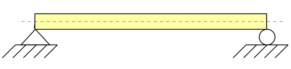
Think of a plank of wood resting on concrete blocks, one block at each end. This is a simply supported beam. The blocks do nothing to prevent the plank from sagging in the middle. This is the model that we will use for our calculations. This is how we symbolize a simply supported beam:
We see a support at either end and an axis running through the center of the beam. The symbols indicate (for modeling purposes) how the beam is fixed to the supports. In this case the symbolism (in layman’s terms) means that the supports (in our case the legs of the stand) have little or no influence on the stiffness of the beam.
What is Beam Span?
For this article we will assume that all calculations are done for the distance measured between the vertical supports. If there was a center brace, then the space would be from the leg to the brace and NOT from leg to leg. Beam Span is typically designed by the parameter label \(L\). See beam span examples below.
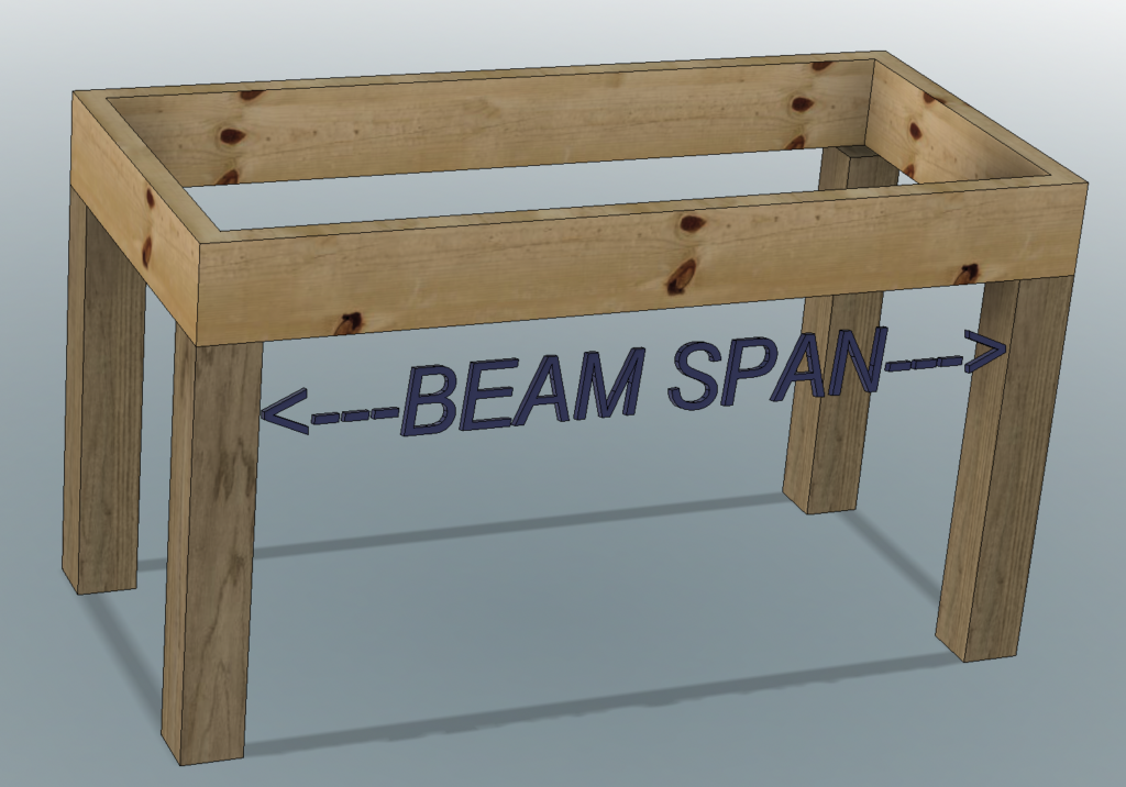
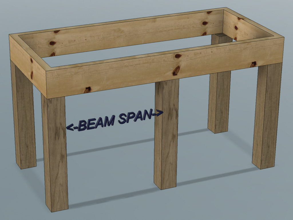
It is important to understand that even if the top of the stand is covered in plywood and has cross braces, the supporting members (beams) that are attached to the legs carry the full load of the aquarium. In the top example there are a total of (4) beams, front, back, left and right. In the bottom example with a FRONT center support and no rear center support there would be a total of (5) beams. front-left, front-right, left, right, back. Typically we would use the beam with the longest span for calculations.
What is Beam Load?
Quite simply Beam Load is the amount of force (weight) acting on a beam span. Below we will discuss two different types of beam load (there are more).
What is a Uniformly Distributed Load?
A uniform load is one where the weight resting on the beam is evenly distributed over the length of the span. The model below shows a uniformly distributed load on a beam.
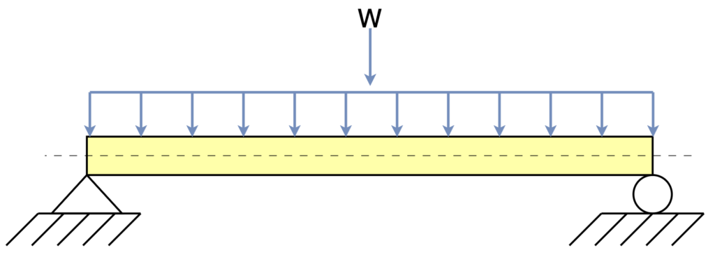
Uniform Beam load is typically designated by the parameter \(w\)or the lowercase Greek letter Omega \(\large \omega\) and a weight per unit length, for example pounds force per foot (\( \textrm{lbf/ft}\)) or pounds force per inch (\( \textrm{lbf/in}\)).
An aquarium resting on a stand is a uniform load. All of the weight of the aquarium is evenly transferred (distributed) over the perimeter of the the stand.
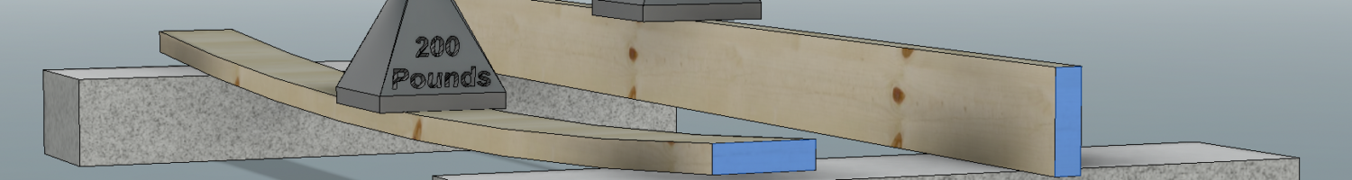
What is a Point (or Concentrated) Load?
A point load (also called a concentrated load) is one where the weight resting on the beam is not evenly distributed over the length of the span. The model below shows a point load on a beam.
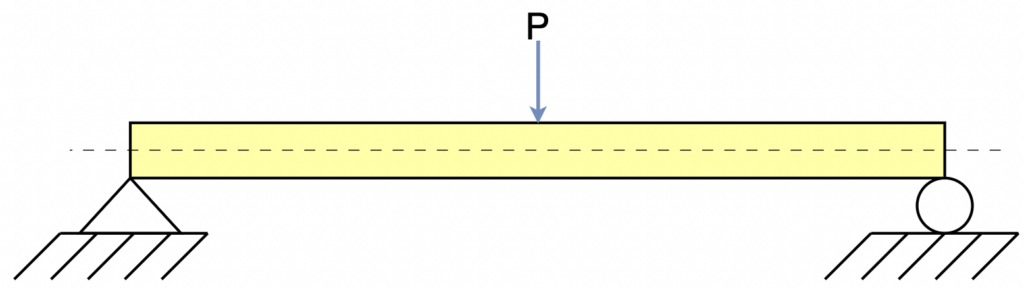
Point (or concentrated) beam load is typically designated by the parameter \(P\) and a total weight, for example pounds (\( \textrm{(lb}\)).
A person standing in the middle of a plank that crosses a moat is an example of a concentrated load.
What is “Beam Deflection”?
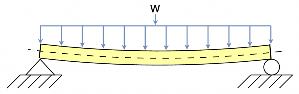
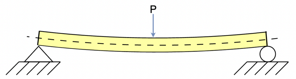
Beam deflection is the distance that beam span deflects (bends) under load. Beam deflection is typically designated by the Greek letter Delta \(\large\delta\).
Example: If a persons stands in the middle of a plank (a concentrated load) that crosses a ditch, their weight will cause the plank to bend or sag to some extent. Likewise a shelf full of the same book end-to-end (a uniformly distributed load) will cause the shelf to sag. The heavier the person (or load of books) and/or the weaker the the beam, the larger the deflection.
Takeaway: Before we can calculate how much a beam will deflect under load, we need to consider the amount of weight and how it is distributed so that we can apply the proper formula.
Note: A beam can carry both uniform and concentrated loads simultanseously .The deflection equations are different for a uniform load and a concentrated load, but their results can be calculated separately and added together to show total deflection under both loads.
What is the Second Moment of Inertia?
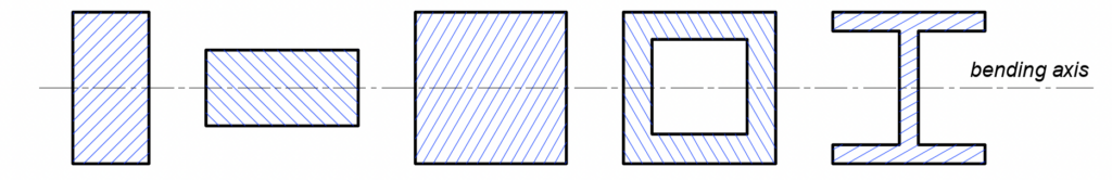
Once again we are going to skip the textbook definition in favor of a layman’s explanation. The Second Moment of Inertia (also known as the Second Moment of Area) is a parameter that describes the ability for a shape, independent of material, to resist bending. The parameter is based on the 2-dimensional cross section of the shape and the direction it is being bent. Second Moment of Inertia is typically denoted by the Variable \(I\). A square tube, a solid bar or an I-beam, etc. all behave differently under load.
The higher the value of \(I\), the less the shape will deflect (bend) under the same load and boundary conditions. Our focus will be on solid rectangular beams and hollow rectangular beams, but the parameter \(I\) can be calculated for any shape.
The takeaway here is that the shape of and orientation of a material greatly effects its ability to withstand bending. Consider two identical pieces of lumber carrying the same weight but oriented differently.
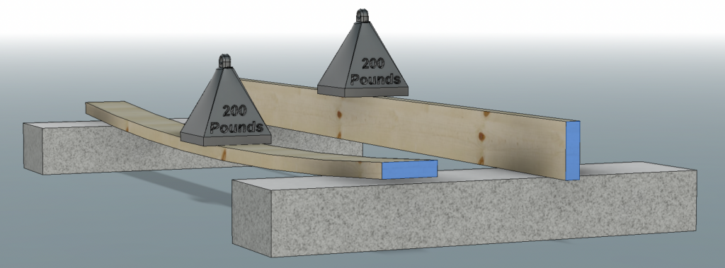
As we can see in the illustration above, not only is the 2-D cross section of the beam important, but so is the direction of the load.
While we can’t look up the values for the Second Moment of Inertia – we can easily calculate it. We will do that in the calculations section.
What isYoung’s Modulus (Modulus of Elasticity)?
Young’s modulus also know as the Modulus of Elasticity is the property of a materials resistance to elastic (recoverable) deformation under load. The Modulus of Elasticity is typically denoted by the variable \(E\).
Note: The elastic part here is key, we are talking only about stiffness, not strength.
- A stiff material has a high Young’s modulus and requires a high load to elastically deform.
- A flexible material has a low Young’s modulus and requires a lower load to elastically changes its shape.
- Do not confuse stiffness with strength – a strong material requires high loads to permanently deform or break. We are calculating bending, not breaking.
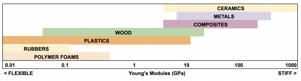
Don’t worry too much about the units, but do notice that the scale above is not linear and instead is logarithmic but we will be dealing with materials that fall into the 1 to 10 GPa range – though we will be using different units, as our calculations will be in Imperials units to match how we measure and eliminate confusing units conversions (more on that later).
The good news is that you don’t need to calculate Young’s Modulus, you will simply look it up in table.
What is Flexural Rigidity?
Flexural Rigidity represents the total stiffness of a beam cross-section and is found by multiplying the Second Moment of Inertia \(I\) which represents the stiffness of a beam cross-section due to its geometry, and the Modulus of Elasticity \(E\) which represents the stiffness of the cross-section due to its material. Flexural Rigidity is typically represented as the parameter \(EI\).
The parameter \(EI\) is an important concept to understand and may be provided in some materials specifications, but we will not use it directly. .
A Note on Units
Numerous unit systems used can be used for science and engineering. This is a source of confusion for many people.
To keep things simple, if you calculate dimensions in decimal inches, then Second Moment of Inertia \(I\) should be in \(in^4\) units and Young’s Modulus \(E\) should be in \(psi\) units and all weights should be in pounds. That output for deflection will be in decimal inches.
I strongly suggest for the scale at which we are working, that inch and pound (or millimeter and gram) units be used and all values converted to that scale. Consult the following table for matching units.
Example Aquarium and Stand for Calculations
Tank size: 51″ Long x 24″ Wide x 32″ High
Support: 3.5″ x 3.5″ legs at all four corners, no center support.
Framing: 2″ x 4″ #2 Southern Yellow Pine (SYP)
Volume: ~160 Gallons
Note: Water weighs ~8.33 pounds per gallon, glass ad rock are denser. A good estimate for aquarium calculations is 10 pounds per gallon to account for the water, tank and rock.
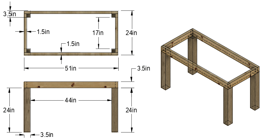
Calculating Beam Span
As we defined above, beam span is measured as the unsupported distance between supports and is designated with the parameter \(L\). There are (4) beam spans in our example stand.
Front and Rear Spans:
\(L=44 \, \mathrm{in}\)
Left and Right Spans:
\(L=17 \, \mathrm{in}\)
We will work with the longer span so:
\(\boldsymbol{L}=44 \, \mathrm{in}\)
Calculating Beam Load
We know the span of the beam and now we can calculate the load on it.
Calculate Total Tank Weight:
\( Weight \,per \,Gallon \times Total \, Gallons = Total\, Weight \)
\( 10 \, \mathrm{lb} \cdot 160 \, \mathrm{gallons}= ~1600 \, \mathrm{lb}\)
\(\boldsymbol{Total \,Weight} = 1600\,\mathrm{lb}\)
Calculate Perimeter Length:
\( Perimeter \,Length = Length + Length + Width + Width\)
\(51+51+24+24=150\, \mathrm{in}\)
\(\boldsymbol{Perimeter \, Length} = 150 \,\mathrm{in}\)
Calculate Distributed Load \((w)\):
\( w = Weight \div Perimeter \, Length\)
\(1600 \, \mathrm{lb} \div 150 \, \mathrm{in} = 10.67 \,\mathrm{lbf/in} \)
\(\boldsymbol{w} = 10.67 \,\mathrm{lbf/in}\)
That takes care of \( \boldsymbol{L}\) and \( \boldsymbol{w}\)
Note: for relatively short spans we do not need to consider the weight of the beam itself and how it may deflect under its own weight. For example, the 2×4 itself weighs \(0.125 \, \mathrm{ lbf/in}\) which is practically irrelevant. However for heavy materials and long spans this added uniformly distributed load becomes significant. In these cases, the weight of the beam itself MUST also be added to the \(\boldsymbol{w}\) parameter
!
Calculating Second Moment of Inertia
The beam is a 2×4 piece of lumber and has a rectangular cross section. Its actual dimensions are 1.5″ x 3.5″ and we will use those for the second moment of inertia calculation.
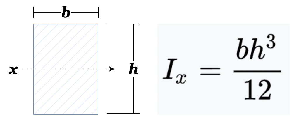
The important thing to understand here is that the bending axis is x, which is perpendicular to the load.
Calculate Second Moment of Inertia:
\( Second \, Moment \, of \, Inertia = (width \times height^3) \div 12 \)
\((1.5 \, \mathrm{in} \cdot 3.5 \,\mathrm{in} \cdot 3.5 \,\mathrm{in} \cdot 3.5 \,\mathrm{in} ) \div 12 = 5.36 \, \mathrm{in^4} \)
\(\boldsymbol{I}=5.36 \, \mathrm{in^4}\)
Young’s Modulus Value
This value is typically looked up in a table provided by the materials vendor. In our example, the 2×6 lumber is #2 Southern Yellow Pine. This is the part where we have to be very careful about units. Thus far we have used inches and pounds for all calculations. We must therefore use (or convert) any looked up \(\boldsymbol{E}\) value to psi.
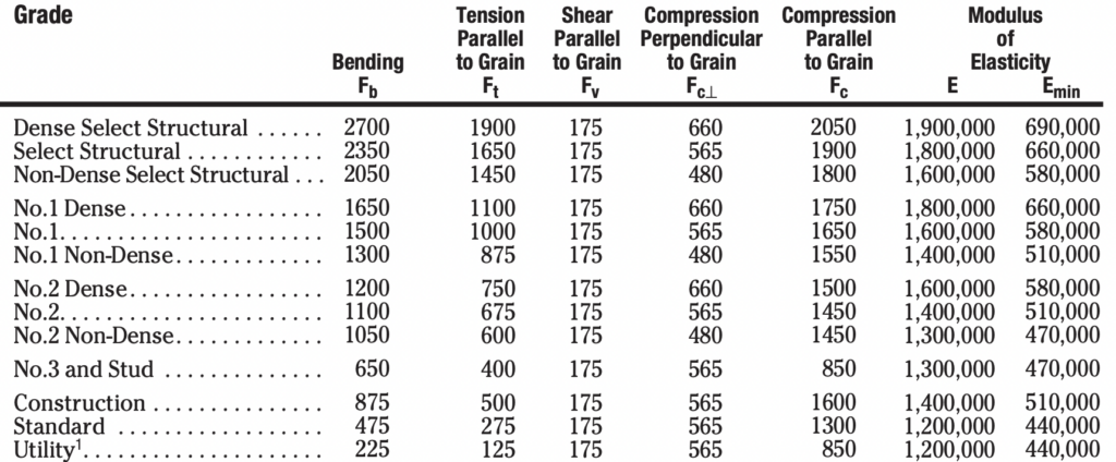
Here is an example table provided by a lumber mill. Luckily the Young’s Modulus (listed as Modulus of Elasticity) are already in units of psi. Notice however, that (2) different values are given for \(\boldsymbol{E}\), a typical value and a minimum value. We will do beam deflection calculations for BOTH to account for typical lumber and for a worst case scenario where a less than ideal piece of lumber is selected.
From the table:
\(\boldsymbol{E}=1,400,000 \, \mathrm{psi}\)
\(\boldsymbol{E_{min}}=510,000 \, \mathrm{psi}\)
Calculating Beam Deflection
We now have everything that we need to do the calculation except for the deflection equation! The equation below is used to calculate the maximum deflection at the center of a uniformly loaded simply supported beam.
\(\boldsymbol{\huge \delta_{max} = {5 \omega L^{4} \over \huge 384EI}}\)
Variables:
\(\boldsymbol{L}=44 \, \mathrm{in}\)
\(\boldsymbol{E}=1,400,000 \, \mathrm{psi}\)
\(\boldsymbol{I}=5.36 \, \mathrm{in^4}\)
\(\boldsymbol{w}=10.67 \, \mathrm{lbf\in}\)
Calculate Deflection:
\({\large 5 \cdot 10.67 \cdot 44^4 \over \large{ 384 \cdot 1400000 \cdot 5.36}}=0.069 \, \mathrm{in}\)
\(\boldsymbol{\large \delta_{max}}=0.069\,\mathrm{in}\)
The deflection value above is for a typical Souther Yellow Pine #2 2×4 using the \( E=1,400,000 \, \mathrm{psi}\) value supplied by the lumber mill. They also provided an \(E_{min}=510,000 \, \mathrm{psi}\) value to account for worst case variations in lumber.
Calculate Deflection (worst case):
The formula is exactly the same, but the lower \(E\) value is substituted.
\({\large 5 \cdot 10.67 \cdot 44^4 \over \large{ 384 \cdot 510000 \cdot 5.36}}=0.19 \, \mathrm{in}\)
\(\boldsymbol{\large \delta_{max}}=0.19\,\mathrm{in}\)
The typical #2 (SYP) 2×4, give this span and load would appear to be sufficient to use for the stand and has a maximum deflection of ~.07 inches. However, if you ended up with a less than ideal piece of lumber, then the deflection of ~0.2 inches would be (in my opinion) not acceptable. That brings us to the question of what is acceptable and safety factor.
Please see the beam deflection calculator and 2nd moment of inertia calculator to go along with this article.
Safety Factor and Deflection
Firstly, the above calculations only take the raw supporting member (the horizontal 2×4 in this case) into consideration. For example: if the stand is covered with a firmly attached plywood skin skinned then plywood will stiffen the beam and carry part of the load. Such calculations are well beyond the scope of this article.
Secondly, the above calculations do not take into account twisting of the beam under load, fasteners, out of level stands and the associated forces, or any outside force such as somebody leaning on the tank or a small tremor (earthquake) etc.
Thirdly, the above calculations assume that material is suitable for the load and deflection is elastic and does not exceed the stress threshold for the material (permanent deformation or failure). These calculations are beyond the scope of this article.
Therefore, a hobbyist or homeowner doing these type engineering calculations should consider them “best case” and for lack of better terms, “over engineer” to some degree. Multiplying either the starting load or final result by some factor and then adjusting the beam size until an acceptable deflection number is reached would be prudent. A multiplier of 3x or 4x would be a good starting point.
What is the acceptable deflection for a fish tank stand? That is a complex question thats answer depends on many factors from span length to tank construction and is also beyond the scope of this article. I would aim for something less than 0.1 inches.
That means for the example aquarium and stand, a 2×6 (or doubled 2×4) would be a much safer beam configuration. I will leave the actual calculations to the reader!
Stay tuned for a calculator on the tools page and Part 2 where we discuss leg size and column buckling!
-Bean
Disclaimer
I make absolutely no claim that the information presented here is accurate, complete or without error in any part or as a whole. Use this information at your own discretion and with the full understanding and agreement that you do so under your own accord and take your own responsibility for any outcomes as a result of using this information for any purpose.


Add comment