
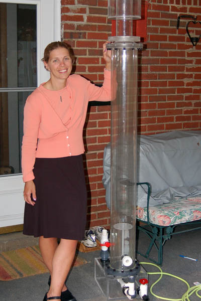
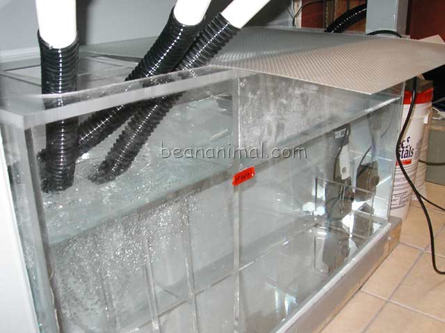
I designed and built this electronic aquarium feeding timer because the “Calfo” style (a.k.a coast-to-coast) overflow setup that I utilize in my system is super efficient at surface skimming. The surface skimming is so efficient that I must shut down the return pump to prevent the food from being quickly skimmed away before the fish have a chance to eat it. I regularly feed premium foods such as the Reef Nutrition Arcti-Pods and Roti-Feast and certainly do not want the bulk of the food in the sump where it will end up rotting or being skimmed out.
Manual Timer aka Pull the Plug
In the past I would simply pull the plug for the return pump to feed the fish. The problem was that I would often forget to plug the return pump back in. One such incident cost me a Yellow Zebrasoma flavescens (Yellow Tang), a Salarias fasciatus (Sailfin/Algea/Lawnmower Blenny) and a Gramma loreto (Royal Gramma Basslet). I suspect the loss was due to the lower oxygen levels in the system that resulted in the severely reduced flow during the photoperiod. It quickly became very clear that I needed an automated fish feeding timer.
Improved Aquarium Feeding Timer
My first aquarium feeding timer was setup using a standard bathroom heat-lamp timer and a relay. I found the timer to be noisy as it wound down and to be honest I did not like the idea of having to give it a twist every night. The timers come in NO (Normally Open Contacts) and NC (Normally Closed Contacts) versions. The NC variety is harder to come by but can be ordered from most electrical supply houses. If you are NOT electronically inclined, then the mechanical bathroom timer is likely your best option for an aquarium feeding timer. I have a short article HERE explaining how to setup such a device. For those of you who are more adventurous, read on…
-WARNING-
The project described below involves working with mains voltages. This information is provided for entertainment purposes only. If you choose to construct a project using this information, you do so at your own risk. I can not be responsible for your safety or the safety of the circuit described here.
Solid State Aquarium Feeding Timer
The initial plan was to use a small microcontroller like a PIC or ATMEL. I went as far as designing and testing the micro based timers. They worked like a charm and will be the topic of another project here at beananimal.com. However, the microcontroller based timers had one problem, most aquarium DIYers are not up to speed (no pun) or equipped to construct microcontroller based projects and I wanted to publish something that would useful to casual aquarists into small DIY projects.
Circuit Requirements
I had a few very simple requirements for the circuit operation.
- silent and reliable operation
- easily adjustable feeding window
- low component count and easy to build
The 555 to the Rescue
What is the next best thing to a microcontroller? Simple! The good ol’ standby known as the 555 timer. If you want to know a little more about the 555, please see the sidebar. The fish feeding timer is based on a simple monostable 555 circuit and a relay to drive the load (the return pump in this case). The 555 is readily available at Radio Shack. You may also find its big brother the 556 that simply contains TWO 555 timer chips in one package. If you are new to electronics, you will want to take a hard look at the 555, as it is the basis for many projects that will expose you to many needed concepts.
Aquarium Feeding Timer Circuit Schematic
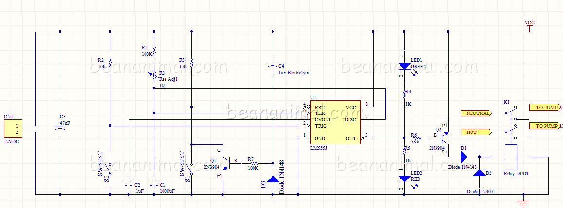
You may also download an Adobe PDF version of the schematic by clicking HERE.
Aquarium Feeding Timer Parts List
Most of the parts (I constructed the project in 2005) can be found at Radio Shack. However, be warned that you will easily end up paying $30 or more for what you need. A much better bet is to order the parts from any online electronics supply or any of the hundreds of eBay vendors who sell surplus electronics components.
LED1 – 5mm Green LED
LED2 – 5mm Red LED
R6 – 5K6 1/4 Watt carbon resistor
R1, R7 – 100K 1/4 Watt carbon resistor
R2, R3 – 10K 1/4 Watt carbon resistor
R4, R5 – 1K 1/4 Watt carbon resistor
R8 – 1M linear taper potentiometer (see text)
C1 – 1000uF ceramic capacitor
C2 – .1µF ceramic capacitor
C3 – 47µF ceramic capacitor
C4 – 1µF electrolytic capacitor
Q1, Q2 – 2N3904 NPN transistor (or similar)
D1,D3 – 1N4148 diode (or similar)
D2 – 1N4001 diode (or similar)
U1 – 555 timer IC
CN1, CN2 2 pole connector (see text)
K1 – SPDT relay (see text)
S1, S2 – Momentary contact switch (Normally Open)
Aquarium Feeding Timer Theory of Operation
The circuit is setup as simple monostable 555 multivibrator, a.k.a a one shot trigger or timer. The heart of the mulivibrator is the 555 timer and the RC network formed by R1+R8 and C1. All of the other components are for circuit protection and added current capacity for triggering the relay.
The monostable circuit produces a single output pulse when triggered. It is called a monostable timer because it is stable in just one state: ‘output low’. The ‘output high’ state is temporary and must be triggered.
The duration of the pulse is called the time period (T) and this is determined by resistor R1 and capacitor C1:
T = 1.1 × R1 × C1 (in our case R1 is the value of R1+R8, we have added R8 so that we can adjust time T as needed).
T = time period in seconds (s)
R1 = resistance in ohms (Ω)
C1 = capacitance in farads (F)
Notes:
Where does the 1.1 come from? The capacitor charges to 2/3 = 67% so it is a bit longer than the time constant (R1 × C1) which is the time taken to charge to 63%.
C1 should be picked first because there are relatively few values available for capacitors. Once you choose C1, you can easily choose R1 by mixing any needed combination of resistors in series. Use a fixed resistor of at least 1k in series if R1 is variable. Electrolytic capacitor values are not accurate, errors of at least 20% are common.
Aquarium Feeding Timer Circuit Description
The timing period (T) is triggered when the trigger (pin 2) is less than 1/3 Vs (the supply voltage), this makes the output high (+Vs) and the capacitor C1 starts to charge through resistor R1. Once the time period has started additional trigger pulses are ignored.
The threshold input (pin 6) monitors the voltage across C1 and when this reaches 2/3 Vs the pulse (timed period T) is over and the output goes low. Discharge (pin 7) is connected to 0V, discharging the capacitor, making the 555 ready for the next trigger.
The reset input (pin 4) overrides all other inputs and resets the timer to its stable state (low).
R2 is s simple pull-up resistor that keeps the trigger (pin 2) high (at Vs) until S2 is closed, pulling it to groun (forcing pin 2 to be less than 1/3 Vs as described above).
R3 is a simple pull-up resistor that keeps the reset (pin 4) high unless the reset button is pressed. This prevents accidental resets due to small fluctuations in circuit voltage. Q1, R7, C4 and D3 are in place to prevent stray capacitance from triggering the circuit during initial power up. R7 and C4 create a small RC network that cause Q1 to conduct (hold the rest pin to ground) until the rest of the circuit becomes stable. The length (time) of this action is roughly R7 × C4. The diode (D3) allows C1 to fully discharge when the power is off.
LED1 and LED2 and their associated current limiting resistors (R4 and R5) are self explanatory. When the 555 timer output is LOW (sinking current) the VCC rail drives LED1 and R4 through the output (pin 3) causing it to light up LED1. When the circuit is triggerd and the 555 output (pin 3) is driven high (sourcing current) the current is driven through LED2 and R5 to the ground rail causing LED2 to light up.
Q2 is situated so that the output (pin 3) of the 555 can drive a larger load, such as a large relay coil. When the output (pin 3) sources current, the transistor drives turns on and drives the relay. D1 directly protects the output (pin 3) from flyback casued by the relay coil and D2 helps to supress the flyback before it ever reaches D1.
C2 and C3 are decoupling capacitors that help to smooth out power supply ripple and ensure stable operation.
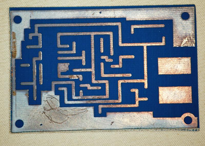
Aquarium Feeding Timer Circuit Construction
The circuit is suitable for perfboard or breadboard construction. I have included a basic PCB layout for those of you who have the skills or desire to work on a PCB instead of perfboard. Care should be taken when soldering the 555 timer, they are tough, but still vulnerable to excess heat. If in doubt, use an IC socket. For the most part, component values are not critical. Just about any small transistor can be used. The MAINS side of the relay should be protected by a suitable fuse, as should the low voltage PCB. The fuses are NOT shown in the schematic but are a MUST for ANY project.
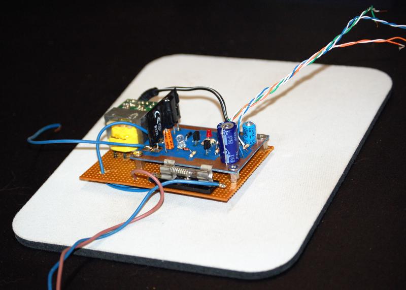
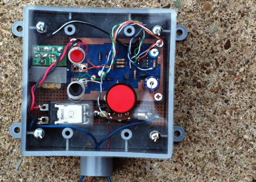
I chose to mount the project into a standard Carlon grey PVC duplex receptacle box. I hacked into a small wal-wart style ac adaptor and mounted its guts inside of the box as well. I used an acrylic cover to mount the switches and adjustment know and mounted the LEDs directly to the PC board. A much simpler option for most DIYers would be to use a project box and AC adaptor from Radio Shack. Many of the project boxes come with a custom fit piece of perfboard.

Operating the Feeding Timer
The timer is very easy to use. The return pump is connected to the Normally Closed side of the relay. During normal operation, the timers output is LOW and the reley is OFF. This allows the return pump to operate as expected. When the trigger button is pushed the timing cycle starts and the relay output transistor conducts, causing the relay coil to pull the relay contacts to the Normally Open position and de-energize the return pump. When the timing period ends, the output transistor stops conducting and the reley returns the the Normally Closed operating position, allowing the return pump to restart.
The timing period can be adjusted by turning the potentiometer. The component values listed in this article (R1, R8 and C1) give a variable timing period from about 2 minutes to about 15 minutes. If R8 is increased to a 2M potentiometer, the timing period can be varied from about 2 minutes to 36 minutes. Please see the 555 Feeding Timer Gallery for more photos.
-BeanAnimal


Add comment